Introduction
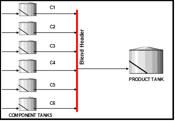
The upgrading of manual fuels blending to an inline fuels blending system requires that blending components flow simultaneously to a common collection point called a blend header. The blend header is a piece of pipe with all component pipes connected along the pipe length and then flowing out from the exit end to the final destination product tank by one pipeline. Figure-1 shows a representative in-line fuels blending system. The design of an automated in-line blending system involves the automation of field equipment, computer hardware, and software, online analyzers, DCS, interfaces, and integration of all these automation modules. These in-line blending automation modules have been discussed greatly in technical literature. However, the design consideration of the fuels blend header is discussed either rarely or none at all in the literature. The purpose of this paper is to present and discuss the design consideration for a fuels blend header.


Figure 1. Representative inline Fuel Blending System
Role of blend header
The role of the inline fuels blend header is to connect all incoming blending components to a common point, mix it well and pump it out to the final product tank. The main criteria for a good blender design are:
- Physical Dimensions – The physical length and diameter of the blend header is determined by the blend rate range and inter-connection distance of component pipelines connected along the header length.
- Mixing – It should have a well-mixed pattern so the final product tank will need to be circulated only for a shorter period or none at all to save energy cost. This will also alleviate the need for a static mixer in the product tank or a separate mixer after the blend header.
- Transportation – The transport of blend components from input tanks to the final blend product tank is facilitated by component tanks’ static pressures and pumps discharge pressures taking into account pressure loss along the way. The blend header pressure should be high enough to flow to the final product tank without a pump between the blend header and the product tank. This will be valid if the product tank is close enough to the header. However, booster pump/s will be needed for remotely located product tanks.
- Component Connections Order – Each blend component differs in properties such as flow rate regime (based on Reynolds number), density, and RVP and accordingly dictate their connection order along the blend header length to ensure proper mixing of heavy (density) and more evaporative (RVP) material.
Design parameters
In this section, we will discuss the design procedures for each of the design parameters for the blend header.
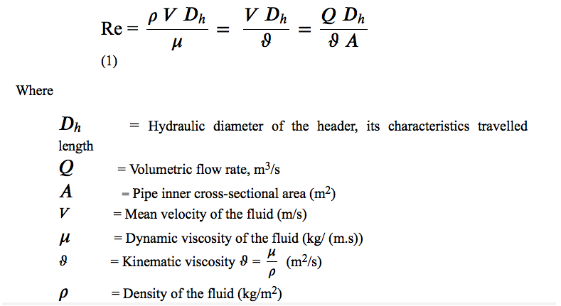
- Physical dimensions – Diameter and length of a blender header are based on the flow regime (laminar versus turbulence) for components entering the blend header as well as blended product flowing thru and exiting the header. Reynold (Re) number measures the degree of flow regime as follows:


Equation (1) can be transformed to calculate the hydraulic diameter of the header as follows:


The recommended range of Re is > 4,000 for a turbulent regime ensuring adequate mixing. However, in reality, Re is much higher than 4,000 as shown in Table-1 for various fuel types. Usually, the blend diameter for gasoline fuel ranges between 12-18 inches, still ensuring a turbulent flow regime. Table-2 shows typical component data for a gasoline blend system with component pipeline diameters ranging between 3-10 inches and Reynold number in turbulent regime [1,2,3] This ensures a thorough mixing in the blender at the points of component connections.
We have assumed a blended rate of 12,000 BPH for a gasoline blender for illustration purposes.


Table 1. Typical Fuels Properties and Blend headers diameters


Table 2. Estimation of Blend Header Diameter for various Fuel Blenders


Table 3. Typical Blend Component Properties and Pipelines Diameters
The length of the blender header is determined again by considering fully turbulent flow and is characterized by Entrance Length (Le). This is the distance for flow to achieve a fully developed state when suddenly changed from the pipe entrance. The component flow enters the header across and not along and thus disturbs the flow pattern in the blend header. Hence, a certain distance must be allowed between two connection points of the component at the blend header to allow the full development of the flow regime again. Figure-2 shows the concept of entrance length and is determined as follows for laminar and turbulent flow [4].


Figure 2. Entrance length for fully developed flow


As all of the component flows are in the turbulent region as seen in Table-2, we can calculate the entrance length for each of the components and 𝐿𝑒/𝐷 and it ranges between 25-36. If the blend header diameter is 12 inches, the inter-connection displacement of the blend component can be between 25-36 ft. However, this separation distance can be adjusted up or down depending upon the actual construction of the blending system at the actual refinery site. For a blending system consisting of 12 components, the blend header could be in the range of 300-450 ft. However, there should be longer distances of 40-50 feet between the last component connection points to the blender exit to facilitate a fully developed turbulent flow before entering the product tank.
2. Header Inlet /outlet pressures – Normal path of flow for the blend material is that it starts from a component tank, pump suction/discharge, flow controller, blend header, static mixer (optional), booster pump (optional), and then finally to the product tank. The blend header exit pressure should be greater than a static head of the product tank in case there is no booster pump required due to vicinity of the product tank to the blend header. The hydraulic calculations by the engineers take into account the pressure losses due to valves, strainers, pipe elevations, control valves, pipelines to ensure that final pressure at the blend header inlet is sufficiently high to pump into the product tank without any pump for nearby tanks. A typical range of blend header pressure is 70-80 psi indicating a pressure drop of 30-35 psi from pump discharge (110-115 psi) to blend header pressure inlet [3, 5, and 6].


Figure 3. Typical PI&D for a blending component circuit
3. Mixing – It is important that the final blend product be mixed thoroughly without any pockets and/or segregation of its qualities. Hence, refiners adopt various additional methods to mix the product well before dispatching to customers and these mixing methods can be applied individually or together depending upon refinery facilities.
-
- Internal Tank Mixers – Some product tanks may be equipped with internal mixers to facilitate final mixing. It is very rarely employed except in the case of old plants and manual blending systems.
- Recirculation pumps – After the blend is completed, the product tank is recirculated for 6-8 hours for manual blending and maybe 2-3 hours for inline blending. Since in-line blending already has a well-mixed product due to its turbulent flow regime in the header, some refiners still prefer to recirculate the tank to avoid any concentered quality pockets.
- External Static Mixer – In addition to or instead of product recirculation, refiners install another static mixer after the blend header and before the product tank. It is sometimes important to use a static mixer if the product tank is further away from the blend header such as export quality blends stored away in distant tanks and must be pumped using a booster pump.
- Internal Tank Mixers – Some product tanks may be equipped with internal mixers to facilitate final mixing. It is very rarely employed except in the case of old plants and manual blending systems.
4. Order of components connection – A blending system typically mix 6-12 components for gasoline blend and 4-8 for diesel and fuel oils blends and connects to a blend header for an inline blending system. The blend components have different properties and play different roles in the mixing of a blend in the header. There are three properties, namely, Reynolds number (as we discussed earlier), Density, and Reid Vapor Pressure (RVP), that affect the way the components should be connected to the blend header.
Flow regime (Re)
It is important that component flows coming into the blend header are in the turbulent flow regime as determined by the Reynolds Number (>4000). The use of the component flow rate is incorrect as even the higher flow rate can be in a laminar regime based on the component pipeline diameter. The component with the highest to lowest Reynolds number should be connected to the header in the farthest to closest order concerning the blend header outlet point.
Density
The component density determines the inertia to movement and is hence related to mixing. The heavy component should be connected farthest from the blender exit point to facilitate mixing while flowing to the exit.
Reid Vapor Pressure (RVP)
The component vapor pressure relates to the amount of vapor present in the gas-liquid mixture of the component. A higher RVP generates a higher amount of vapor. Hence, components with higher vapor pressure should be connected farthest from the header exit point to facilitate proper gas-liquid mixing while flowing to the exit.
We used the component properties data shown in Table-2 and sorted the component in the order of individual properties, Reynold number, Density, and Reid Vapor Pressure. Each parameter has its own characteristics, Components with heavier density tend to settle, and components with higher RVP generate more vapor phase. The turbulent flow ensures that as the components enter the blend header along the length, they have both vertical and horizontal mixing without any quality segregation (may be subtle but would avoid product recirculation to achieve mixing).
This sorted order is shown in Table-3 and does not give us any definite connection order of components. Hence, we used the statistical weighted average method by assigning the weight to each of these properties as follows by using engineering judgment and our extensive experience with fuel blending system project implementations. In addition, this methodology should be used as a guideline and one can use different factors based on their own preference and experience.
For Gasoline Blend
Reynolds Number – 65%
Density – 25%
Vapor Pressure – 15%
For Diesel Blend
Reynolds Number – 65%
Density – 35%
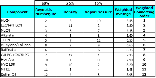
Table-4 shows the component connecting order based on a sorted weighted average of component properties for gasoline blends.


Table 4. Statistically weighted Ranking Based on Re, Density, and RVP
Figure-4 shows the graphical diagram of the component connection order for the gasoline blend header.


Figure 4. Gasoline Blender with weighted orderly Connected Component
We can also calculate the component connection orders for diesel and fuel oil blenders using the same methodology as discussed in this paper.
Summary
We have discussed the design of a fuels blend header for an inline blending system in terms of its physical dimension, inlet/exit pressures, mixing methods, and most importantly how components should be connected to the blender header based on their properties.
References
- http://www.engineeringtoolbox.com
- http://www.vicopedia.com
- S-Oil Refinery, Seoul, South Korea Blending revamp project FEED Review consultation by authors
- https://www.eng.fsu.edu/~shih/eml3016/lecture-notes/pipe%20flow%20considerations.ppt
- OMS Webinar “Design of Fuel Blend header”, June 2015
- OMS Training Course Manual “Strategic Fuel Blending Technology and Management”
About the authors
Dr. Suresh Agrawal is the founder and CEO of Offsite Management Systems LLC (OMS), Houston, Texas, USA. He graduated from the Indian Institute of Technology, Mumbai, India with a Bachelor of Chemical Engineering. He then obtained his Master’s and PH.D. Degrees in Chemical Engineering from Illinois Institute of Technology, Chicago, USA.
Dr. Agrawal has 30+ years of experience with senior technical/management positions at international companies, and he has successfully managed many advanced refinery process control projects in numerous countries. Dr. Agrawal is a registered professional engineer in the state of Illinois, USA, and is a member of the American Institute of Chemical Engineers and Instrumentation Society of America. He has published and presented 20+ papers in international publications and conferences in the areas of advanced process control. He has also acted as a consultant to a number of refining and process industries worldwide and delivers training seminars in the areas of his expertise.
Meena Agrawal is the co-founder and President of Offsite Management Systems LLC (OMS), Houston, Texas, USA. Meena is responsible for project management and execution as well as clients’ relations and business development. She graduated from Roosevelt University with a Bachelor’s degree in Chemistry and an Associate’s degree in Computer Science from Morris County College, New Jersey.
Mrs. Agrawal has 20+ years of experience as a Project Management/technical lead positions with major international companies such as Phillips 66, Exxon-Mobil, Apache Corp and handled projects for windows 7 migration, domain and system separation for ConocoPhillips and Phillips 66, Upstream (EU) application suite for supply and nomination, upstream gas/oil wells test and production data management, etc.
#In-LineBlendingSystem #FuelsBlendingHeader #FlowRegimeRate #OnlineBlendingAnalyzers #BlendingAutomationModules #DcsBlendModel #ReBlendComponent #RvpOnlineAnalyzersSystem #DynamicFluidViscosity #ReLaminarFlow


1 2 3 4 5 100%
1 2 3 4 5 0%
1 2 3 4 5 0%
1 2 3 4 5 0%
1 2 3 4 5 0%